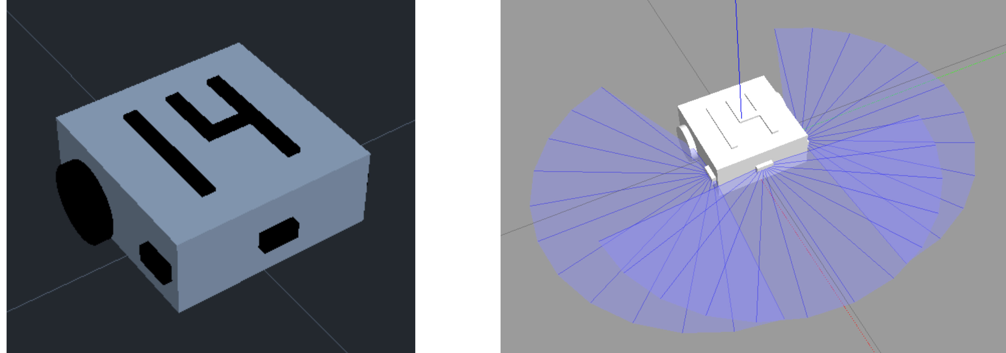
We were introduced to the basics of ROS by designing a two-wheeled robot in URDF format, implemented a velocity control algorithm and an obstacle avoidance algorithm.
- Date: May 2020
- Author: Thomas Kimble, Chantal Gressier, Ken Pillonel
- Field of Study: Robotics, ROS, URDF, Python
- Context: EPFL Ma-2 Robotics Practicals Project
Goal
The aim of this project was to go through the basics of ROS, first by designing a two-wheeled robot, then by implementing a velocity control algorithm and finally an obstacle avoidance algorithm. It was a good exercise to learn about communication between different nodes (publishers/subscribers). The design of the robot was done in the URDF format and the navigation algorithm of the robot was implemented thanks to Gazebo plugins through a few Python scripts. We used Gazebo to visualize and test our solution.
Robot Model
Our robot model is based on the existing Thymio Robot. It has a rectangular shape with two cylindrical wheels on each side, and a sphere at the front to keep the robot level. This gives us three degrees of freedom (DOF = 3: Tx, Ty and Rx) and a mobility of M = 2.
We added three sensors, one at front of the robot and one on each side, which are used for the obstacle avoidance algorithm. We use three to allow for accurate wall following in both left and right directions. The model description was written in the URDF format through an XML file. The robot is shown below with its dimensions and the following origin points:
- MP: Main Body Link Origin
- RW: Right Wheel Joint Origin
- LW: Left Wheel Joint Origin
- S: Structural Sphere Origin
Here is a quick schematic of the robot and its dimensions (in mm) with the different origin points for the URDF links and joints:

After adding our group number to the robot as well as a few sensor plugins, we could visualise it in Rviz and Gazebo:

Velocity Control
In order to make the robot move from an initial position to a goal position, we used Gazebo’s differential drive plugin and computed the motion of the robot in a Python script. The velocity control algorithm is composed of two main controllers a PD controller for the position and another PD controller for the angle with a speed threshold.
To make the robot move, a certain trajectory is given to the robot through waypoints by subscribing to a goal position topic where the goal positions are published by the user. Once the goal is set, a control loop is responsible for publishing the appropriate velocities to the odom Topic to move the robot to the correct waypoint.
Obstacle Avoidance
We use a finite state machine to switch between waypoint navigation and obstacle detection. Navigation is done in STATE = 0 where we check for obstacles at each time step. If an obstacle is detected we start a left or right wall following algorithm to avoid the obstacle. Left obstacle contouring is done in STATE = 1, and right contouring is done in STATE = 2. The state is chosen depending on which sensor is closer to the wall. Sensor values are read by subscribing to laser_side/scan topics.
The avoidance is done in three parts and is illustrated in the figure below:
- Obstacle detected. Approach wall and left or right
- Left or right wall following
- If angle error is lower than a threshold value switch to navigation state

Video Demonstration
Additional Material
For any more information on the project, please don’t hesitate to contact me here, or check out the report and code below.


