
We created a precise line following algorithm for the e-puck2 robot thanks to the addition of 3D printed hardware and a mirror, bypassing the robot’s sensor limitations.
- Date: May 2019
- Author: Thomas Kimble, Adrien Ohana
- Field of Study: Robotics, C++, CAD
- Context: EPFL Ba-6 Embedded Systems and Robotics Project
Goal
We were asked to create our own project using the e-puck2 robot, with the only instructions being to demonstrate its capabilities using all of its main sensors and actuators. Inspired by autonomous vehicles, we decided to create a line following algorithm with a track that included junctions or intersections. This would allow us to send sound commands to the robot to tell it which way to go at an intersection.
Method
The robot detects the line and intersections using the on-board camera and some image processing, and corrects each motor speed by executing a P controller to make it turn. An intersection is detected when the track starts to get thicker and reaches a threshold. Once an intersection is detected, the robot stops and awaits instructions. We use audio signal processing to detect the frequency of the sound remote and once an instruction is heard, the LEDs act as turn signals and the motors follow a predetermined path to follow the track in the wanted direction. Finally if the robot’s TOF sensor detects an object, we used a PI controller to keep the robot at a safe set distance to any of the obstacles or moving objects ahead of it.
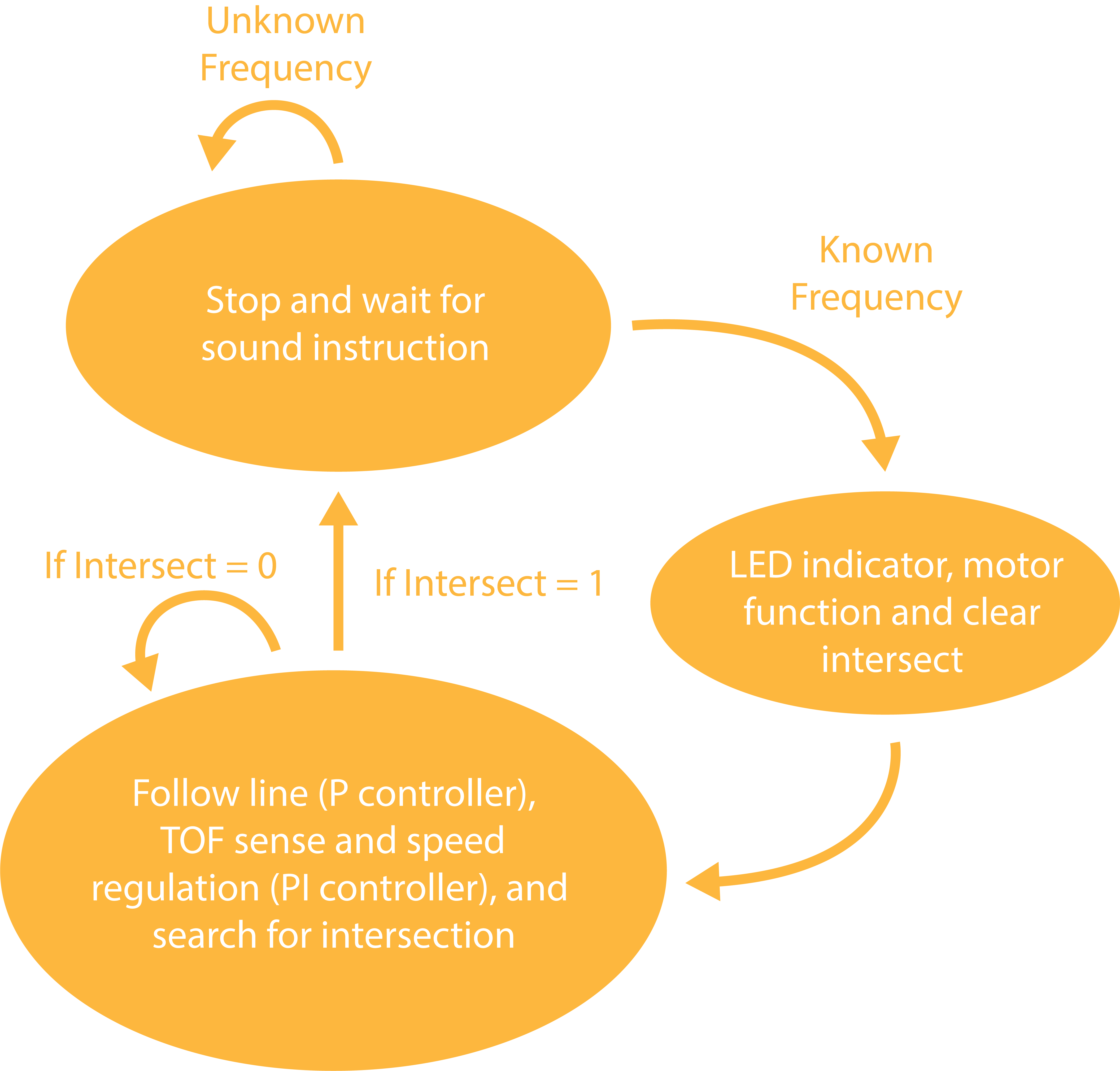
This was our first introduction to threads so we wanted to make the most of this newly discovered feature by allowing our robot to execute multiple tasks at once. We used a state machine with three states each executing multiple threads at once:
- State 1: Follow Line, TOF sense, and search for intersection
- State 2: Stop and wait for sound instruction
- State 3: LED direction indication, motor function to change direction and clear intersection
Sensor limitations
We wrote some code to detect a line on a piece of paper using the robot’s on board camera which worked well. We implemented a P controller for motor speed regulation, but realised that the forward facing camera was not great at following lines below it. Despite using the pixels of the lower part of the sensor, the robot would not follow lines precisely as demonstrated in the video below.
We decided that we would create additional hardware to mount a mirror in front of the robot’s camera, allowing it to face straight down in front of it. We tested with some metal wire and the results were promising, and after multiple 3D printed iterations we ended up with a robust version seen in orange below.
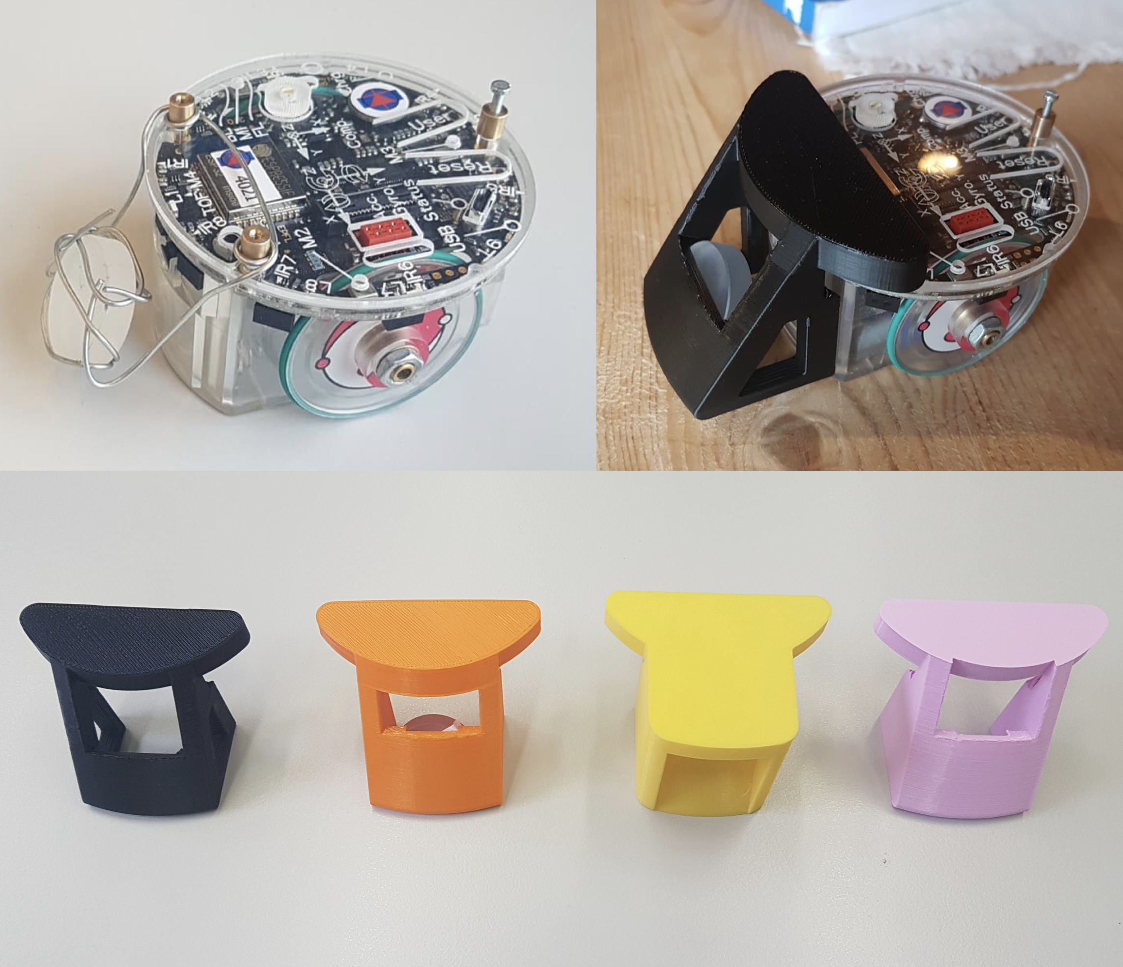
I created the piece in Catia V5, my go-to CAD software. Some fiddling in Blender allowed me export the models in the .glb format, letting us showcase a more detailed view here.
Line Following Track
The robot can follow lines of thickness between 0.4 and 1cm with a minimum turn radius of 7.5cm. The robot detects an intersection when it notices a line thickness between 1.6 and 2.2cm and needs to be heading in a straight direction. We therefore define a Stop Triangle as shown here:

We can combine up to four Stop Triangle to create intersections where the robot stops and awaits one of four instructions from the sound remote. This allows us to create tracks where the robot can follow lines, arrive at intersections and await instructions.
An example of such a track can be found below. You can get quite creative! We even tried drawing tracks with a thick pen, which worked, but intersections are more tricky.

Sound Remote
We created a simple app with four buttons for each instruction, which generates a frequency detected by the robot.
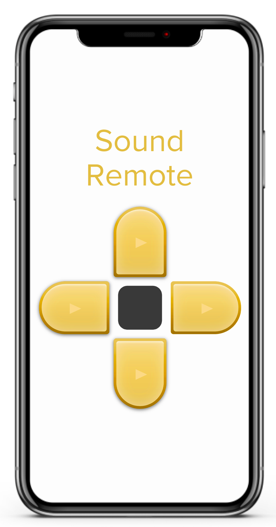
| Instruction | Button | Sine Wave Frequency |
|---|---|---|
| Skip Stop | ↑ | 2000 Hz |
| Left Turn | ← | 3000 Hz |
| Right Turn | → | 4000 Hz |
| U Turn | ↓ | 5000 Hz |
Results
We created additional hardware allowing us to mount a mirror on to the e-puck2 robot. Along with robust code, the robot could manage precise line following. We were happy with the project and were nominated for the GCtronic award given by the manufacturers of the robot, meaning we were in the top 6 projects of the class.
Although we don’t have a video of the final results on a track such as shown above, we have an earlier version for you to check out here:
Additional Material
For any more information on the project, please don’t hesitate to contact me here, or check out the report (in French) and code below.

